Orthogonal Multi-Carrier Modulation

Orthogonal Multi-Carrier Modulation Orthogonal Multi Carrier (OMC) communication systems aim at increasing the transmission medium capacity (bits/Hz) by modulating information (bits) onto different sub-carriers and combining all the sub-carriers into a single time domain signal stream for transmission. On the receiving end, information on each sub-carrier is extracted from the combined signal. In theory, capacity of the transmission medium increases linearly with the number of sub-carriers a transmission medium can accommodate.

Two-Carrier Communication System

Suppose that two Single-Carriers (SC) with symbol periods \(T_1\) and \(T_2\) are amplitude modulated with information \(A\) and \(B\) respectively, the combined signal \(S(t)\) can be described mathematically as in below equation,

\begin{equation}\begin{split} \label{eq:TCM} S(t) &= S_1(t) + S_2(t) \\ &= A \sin\left(\frac{2\pi t}{T_1}\right) + B \sin\left(\frac{2\pi t}{T_2}\right) \end{split}\end{equation}

Demodulation Challenges

Requirements by the receiver to extract the information from each of the two sub-carriers are,

  1. Knowledge of Symbol durations \(\left[T_1, T_2\right]\) (time over which a unique information is transmitted on each sub-carrier).
  2. Ability to extract information from each sub-carrier without interference from the other.

First, let us try to demodulate the individual information on sub-carriers from the combined signal \(S(t)\) in-order to design \(\left[T_1, T_2\right]\) values. Information on sub-carrier \(T_1\) can be extracted by correlating the combined signal \(S(t)\) with \(\sin \left( \frac{2 \pi t}{T_1} \right)\)

\begin{equation}\begin{split} \hat{A} &= \frac{2}{T_1} \int_{0}^{T_1} S(t) ~\sin\left( \frac{2 \pi t}{T_1}\right) ~dt \\ \nonumber &= \frac{2}{T_1} \int_{0}^{T_1} S_1(t) ~\sin\left( \frac{2 \pi t}{T_1}\right) ~dt + \frac{2}{T_1} \int_{0}^{T_1} S_2(t) ~\sin\left( \frac{2 \pi t}{T_1}\right) ~dt \\ \nonumber &= \frac{2}{T_1} \int_{0}^{T_1} A ~\sin^2\left( \frac{2 \pi t}{T_1}\right) ~dt + S_2(t)_{Intf} \\ \nonumber &= A + S_2(t)_{Intf} \end{split} \label{eq:s1} \end{equation}

\(S_2(t)_{Intf}\) is the inference from sub-carrier \(T_2\). Similarly, information on sub-carrier \(T_2\) can be extracted by correlating the combined signal \(S(t)\) with \(\sin \left( \frac{2 \pi t}{T_2} \right)\)

\begin{equation}\begin{split} \hat{B} &= \frac{2}{T_2} \int_{0}^{T_2} S(t) ~\sin\left( \frac{2 \pi t}{T_2}\right) ~dt \\ \nonumber &= \frac{2}{T_2} \int_{0}^{T_2} S_2(t) ~\sin\left( \frac{2 \pi t}{T_2}\right) ~dt + \frac{2}{T_2} \int_{0}^{T_2} S_1(t) ~\sin\left( \frac{2 \pi t}{T_2}\right) ~dt \\ \nonumber &= \frac{2}{T_2} \int_{0}^{T_2} B ~\sin^2\left( \frac{2 \pi t}{T_2}\right) ~dt + S_1(t)_{Intf} \\ \nonumber &= B + S_1(t)_{Intf} \end{split} \label{eq:s2} \end{equation}

\(S_1(t)_{Intf}\) is the inference from sub-carrier \(T_1\). Let us analyse the interference terms \(S_1(t)_{Intf}\) and \(S_2(t)_{Intf}\) to design the values for \(\left[T_1, T_2\right]\). Suppose that \(T_1\) is greater than \(T_2\) then for any positive integer \(n\) we can write \(T_1\) as,

\begin{equation}\begin{split} T_1 = n T_2 + \left(T_1 - n T_2\right) \end{split}\end{equation}

we can re-write the interference terms as,

\begin{equation}\begin{split} S_2(t)_{Intf} &= \left\{ \begin{array}{lll} \begin{aligned} \sum_{k=1}^n \frac{2}{T_2} \int_{(k-1) T_2}^{k T_2} S_2(t) \sin\left( \frac{2 \pi t}{T_1}\right)dt \\ ~+ \frac{2}{(T_1 - n T_2)} \int_{n T_2}^{T_1} S_2(t) \sin\left( \frac{2 \pi t}{T_1}\right) dt \end{aligned} \end{array} \right. \\ \nonumber &= \left\{ \begin{array}{lll} \begin{aligned} \sum_{k=1}^n \frac{2 B_k}{T_2} \int_{(k-1) T_2}^{k T_2} \sin\left( \frac{2 \pi t}{T_2}\right) \sin\left( \frac{2 \pi t}{T_1}\right)dt \\ ~+ \frac{2 B_{n+1}}{(T_1 - n T_2)} \int_{n T_2}^{T_1} \sin\left( \frac{2 \pi t}{T_2}\right) \sin\left( \frac{2 \pi t}{T_1}\right) dt \end{aligned} \end{array} \right. \end{split} \label{eq:s2_intf} \end{equation}

\(\{B_k\}\) is information transmitted on \(T_2\) carrier in kth symbol duration.

\begin{equation}\begin{split} S_1(t)_{Intf} &= \frac{2}{T_2} \int_{0}^{T_2} S_1(t) \sin\left( \frac{2 \pi t}{T_2}\right)dt \\ \nonumber &= \frac{2 A}{T_2} \int_{0}^{T_2} \sin\left( \frac{2 \pi t}{T_1}\right) \sin\left( \frac{2 \pi t}{T_2}\right)dt \\ \end{split} \label{eq:s1_intf} \end{equation}
  1. Integral equation \(S_1(t)_{Intf}\) goes to zero, if \(T_1 = n T_2\) for any positive integer \(n\). So, separation between the sub-carriers in frequency is related by the expression \(T_1 = n T_2\) and the pair \(\left[T_1,T_1/2\right]\) will be the minimum separated orthogonal sub-carriers. Any number orthogonal-carrier system can be designed based on this result.
  2. Integral equation \(S_2(t)_{Intf}\) goes to zero, if all \(\{B_k\}\)'s in \(T_1\) duration are same. So minimum symbol period for a multi-carrier system design is equal to the symbol period of minimum distant sub-carrier frequency from DC.

Two-Path Transmission Channel

Transmission medium with multiple delay paths between transmitter and receiver introduce inter-symbol interference (ISI) and also compromise the orthogonality between the sub-carriers in a multi-carrier communication system. Let us analyze a two-tap multi-path channel with channel tap delays \(\left[0,\tau\right]\). For the sake of simplicity let us assume that both channel tap gains are 1, and time domain channel can be described mathematically as \begin{equation} h(t) = \delta(t) + \delta(t - \tau) \end{equation}
If the signal described in Figure 3 is passed through channel \(h(t)\), the received signal would be as described in Figure 5, dotted lines describe the signal corresponding to multipath delay \(\tau\).

Resolve Inter-Symbol Interference (ISI)

If the knowledge of maximum delay path is known, mute-periods can be introduced between consecutive data symbol periods to mitigate inter symbol interference. A zero-padded transmission output of a two path multi channel would be as shown in Figure 6
Corresponding recieved signal will be as described in Figure 7
It can be observed that mute-periods (zero-padding) could mitigate ISI but the orthogonality between the sub-carriers is not retained due to multi-path transmission channel. Sub-carrier interference terms due to multi path tranmission can be computed as described below
\begin{equation}\begin{split} S_1^{\tau}(t)_{Intf} = \frac{2 A}{T_1} \int_{\tau}^{T_1} \sin\left( \frac{2 \pi t}{T_1}\right) \sin\left( \frac{2 \pi t}{T_2}\right)dt \\ \nonumber S_2^{\tau}(t)_{Intf} = \frac{2 B}{T_1} \int_{\tau}^{T_1} \sin\left( \frac{2 \pi t}{T_1}\right) \sin\left( \frac{2 \pi t}{T_2}\right)dt \\ \end{split} \label{eq:s_intf} \end{equation}

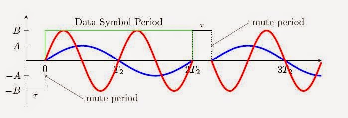
Retain Sub-carrier Orthogonality

Multi path received signal can retain sub-carrier orthogonality only if the integrals \(S_1^{\tau}(t)_{Intf}\) and \(S_2^{\tau}(t)_{Intf}\) are zero's. This can be achieved if a known signal is transmitted during the mute-periods, that can make the interference integration limits as \(\left[0,T_1\right]\). This problem can be solved if we pre-fix some part of tail of each data symbol to its start, popularly known as Cyclic Prefix in Orthogonal Frequency Division Multiplexing (OFDM) system.

Adding Cyclic prefix to the transmitted signal is described in Figure 8 and Figure 9 describes the multipath received signal with cyclic prefix transmission.

No comments:

Post a Comment